Introduction
If your Brother machine is not capable of sharing data through its ethernet port using the MachineMetrics Brother Adapter, it will have to be integrated using the I/O kit. Generally, we are able to collect signals for active/idle state, part count, and alarm state.
Topics covered in this article
This article will cover the following topics:
- Locating a usable power source for I/O kit hardware
- Locating an external output terminal block
- Programming outputs on an External Output Terminal Block
- Adapter Script
Locating a Usable Power Source for I/O Kit Hardware
The MachineMetrics I/O hardware is powered by 24 DC volts, sourced from the machine's wiring. All Brother machines have a 24VDC power supply that should be capable of powering auxiliary hardware. To avoid voltage alarms, it may be important to power the MachineMetrics hardware from the same power source as the signals you will be pulling from the machine's circuitry. In most cases, Brother CNCs are equipped with 24VDC power supply that can provide enough power support small electronic devices (minimal amperage draw).
Pictured below is an example of a 24vdc power supply connection to the USB inverter.*
*NOTE: Not all Brother machines will have the same power supply or arrangement.
Locating an External Output Terminal block
Brother CNC machines are generally equipped with at least one block of terminals that are capable of being programmed to be energized in conjunction with certain machine states or functions. For example, if the machine has two pallets, and you want to know when either pallet 1 or pallet 2 are being operated on, you can set an output on the external output terminal block to be energized whenever pallet 1 is in use, and another output to be energized when pallet 2 is un use.
Depending on the model and age of your Brother CNC, the layout of the electrical cabinet will differ. The external output terminal block (XTO for short) will be located on one of the circuit boards in the electrical cabinet. Pictured below is an example of the XTO terminals:
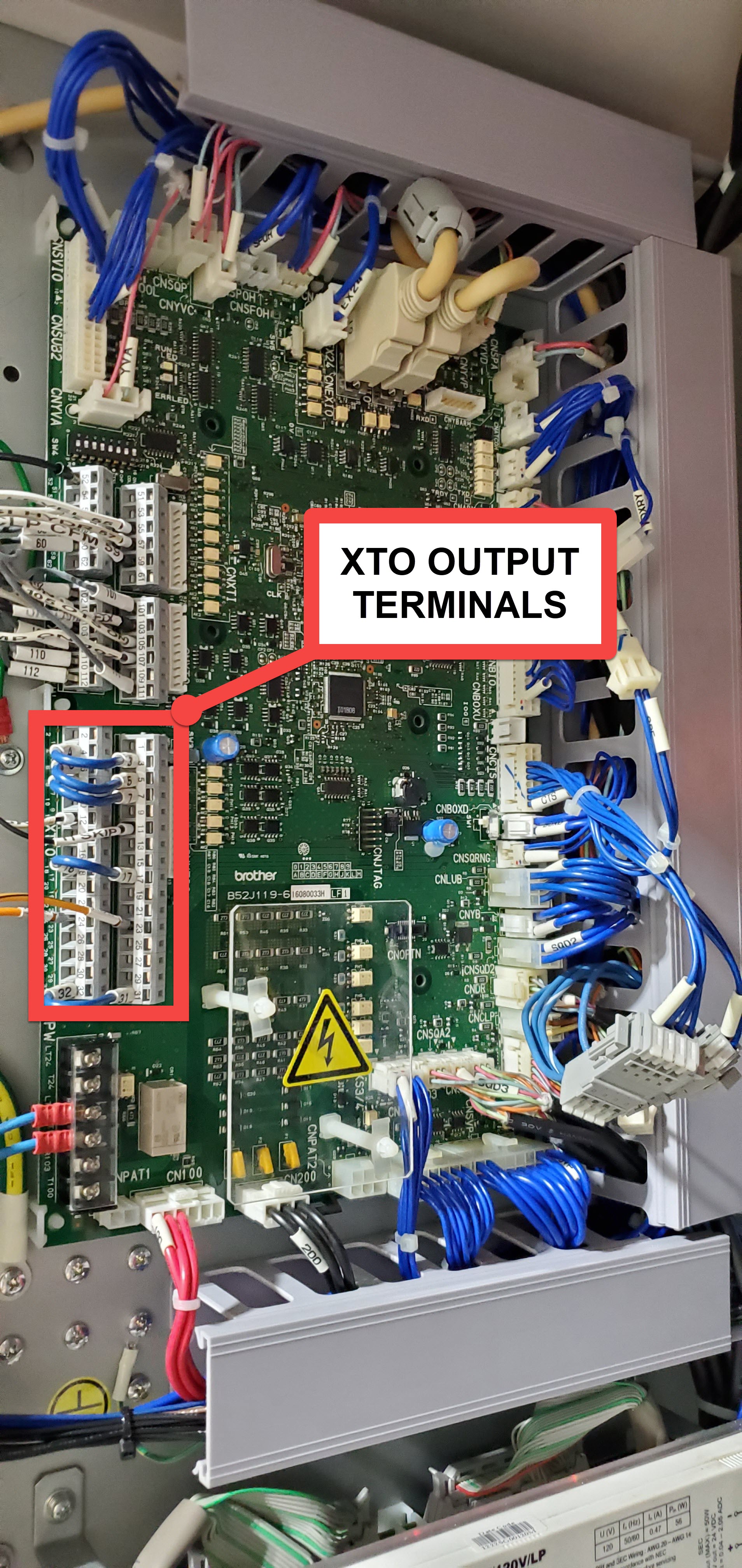
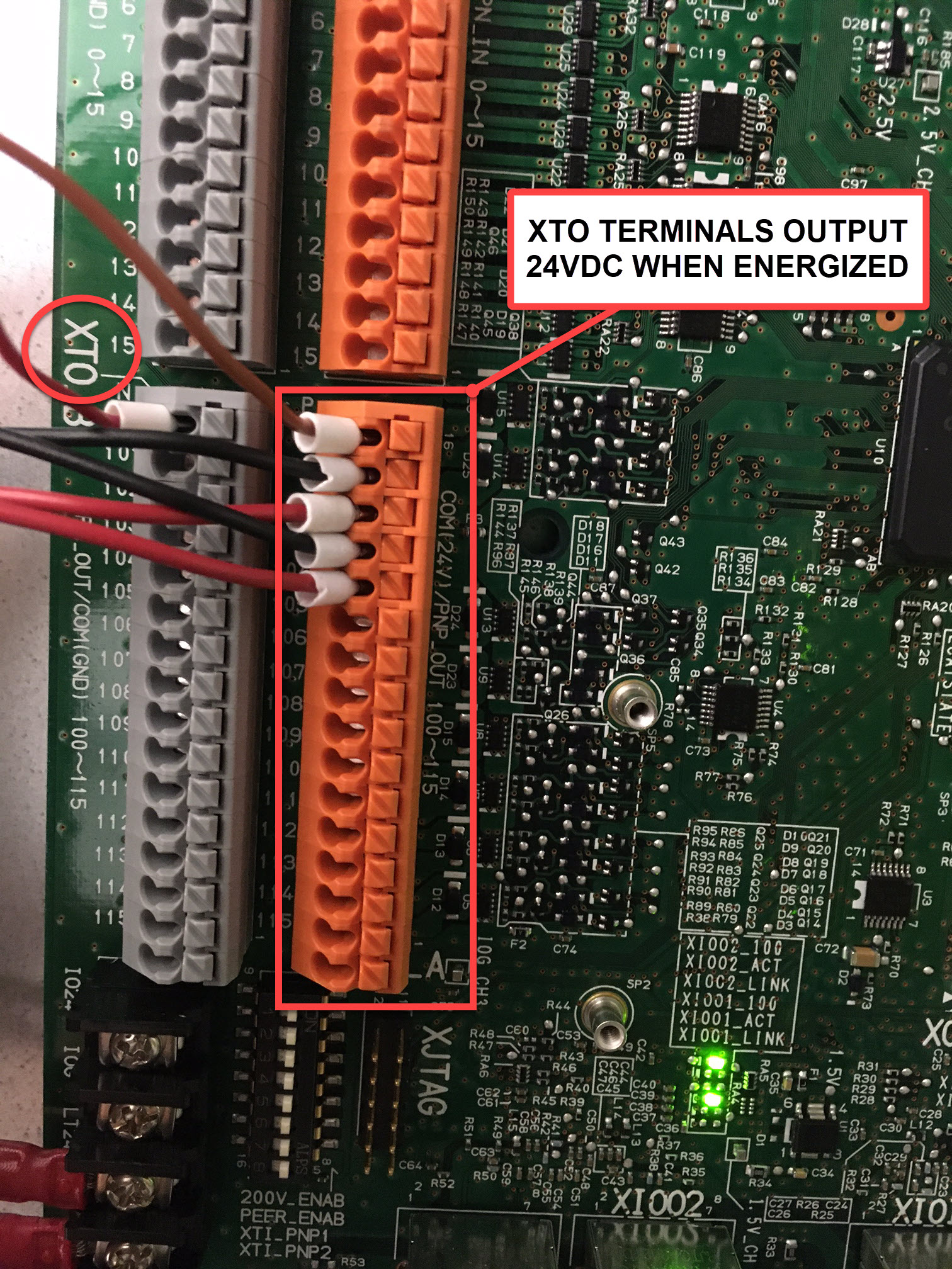
Each terminal will be numbered, and will generally be labeled on the circuit board "XTO" (not to be confused with the "XTI" terminals, which are External Inputs. Pictured below are the XTO terminals of a newer Brother CNC. Notice that the orange terminal block is numbered in the same way as the gray block beside it. They are both XTO terminals, but the orange block (PNP) outputs 24VDC when active, and the gray block (NPN) opens 0V when active. Either can be used, but the outputs that open 0V will have to be used with a relay to transmit the signal to the Labjack.
Programming outputs on an External Output Terminal Block
Now that you've located the physical External Output terminals and have identified 2-3 of them that are unoccupied, you can program those outputs to be energized at certain machine states.
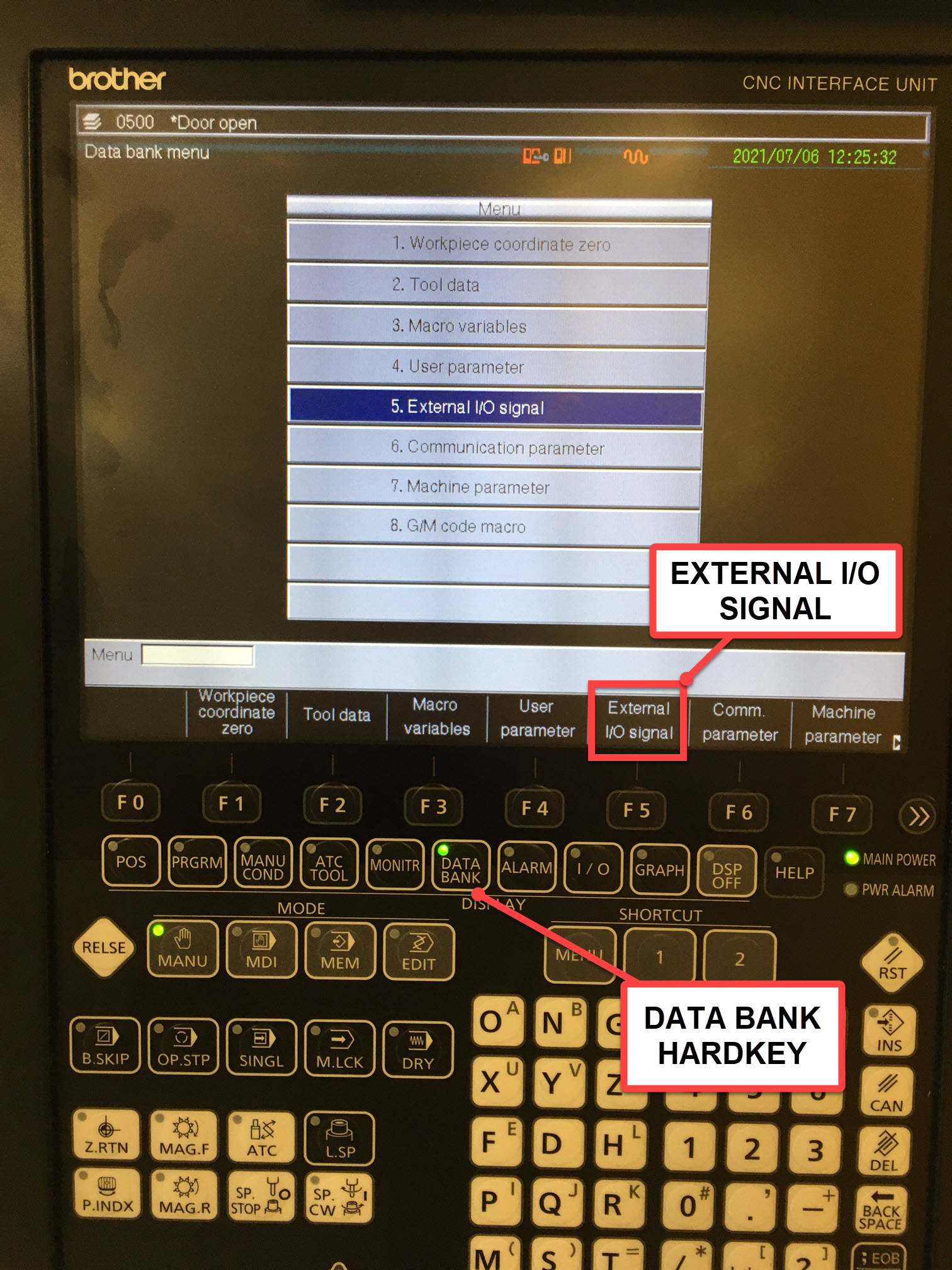
Regardless of the age of your Brother controller, the first place to navigate to is "DATA BANK". In the image below, the DATA BANK hard key has been pressed. If the first screen after pressing DATA BANK looks like this, press the "External I/O Signal" softkey.
If the DATA BANK menu takes you to a screen that looks like what is pictured below, press the "User Parameters" softkey.
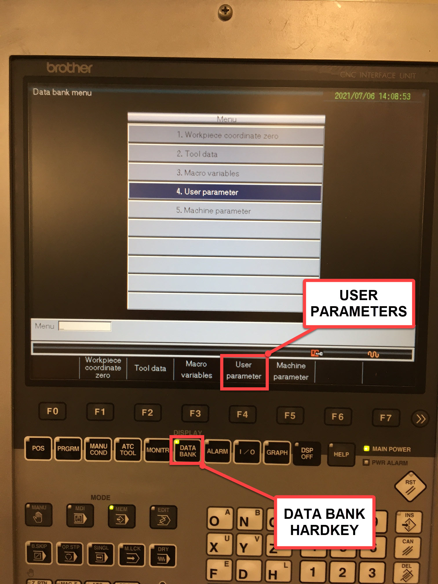
The "User Parameters" softkey will take you to another menu. If "External I/O Signal" is not on the proceeding menu, click the "Next Menu" softkey, as pictured below:
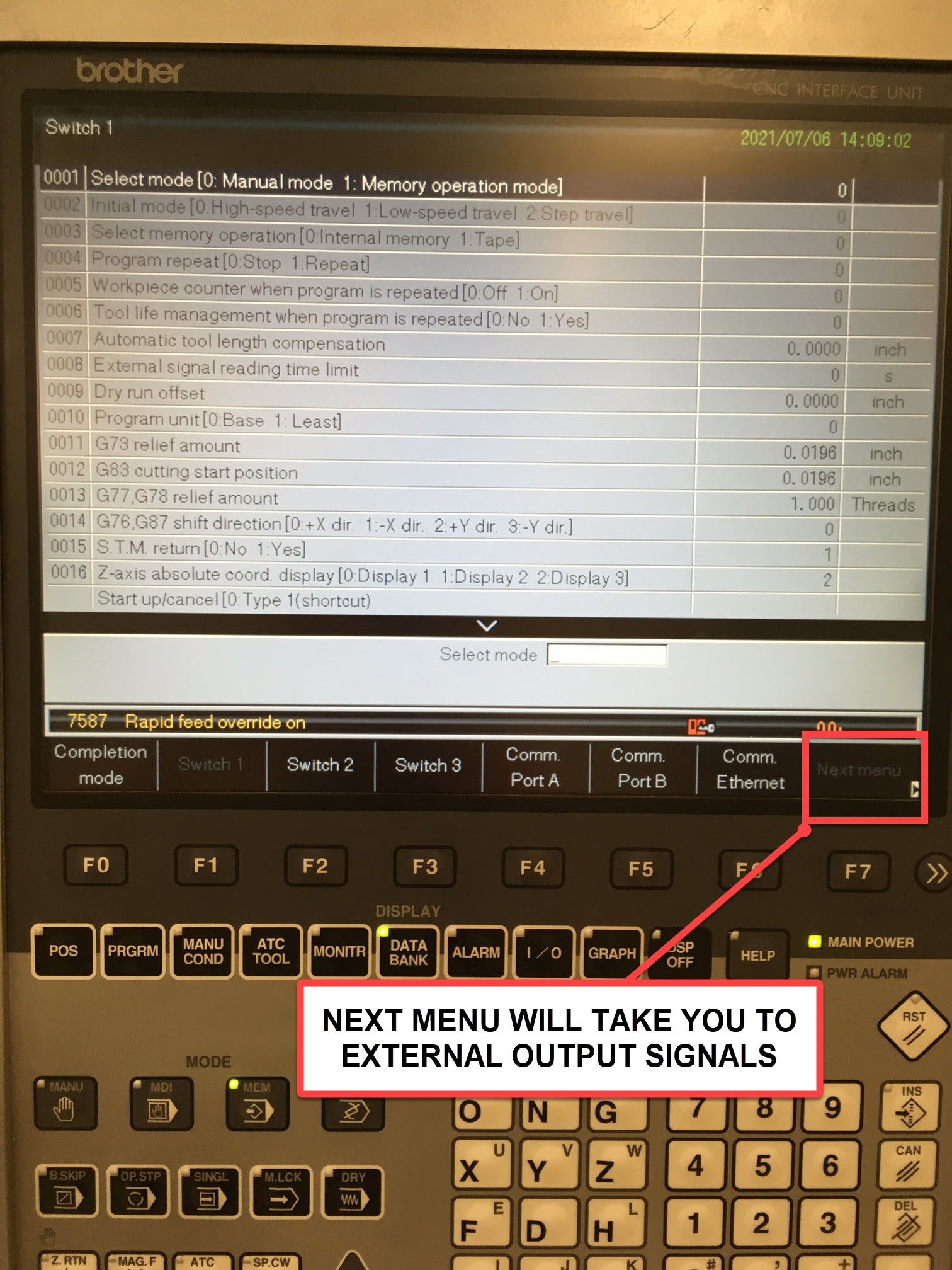
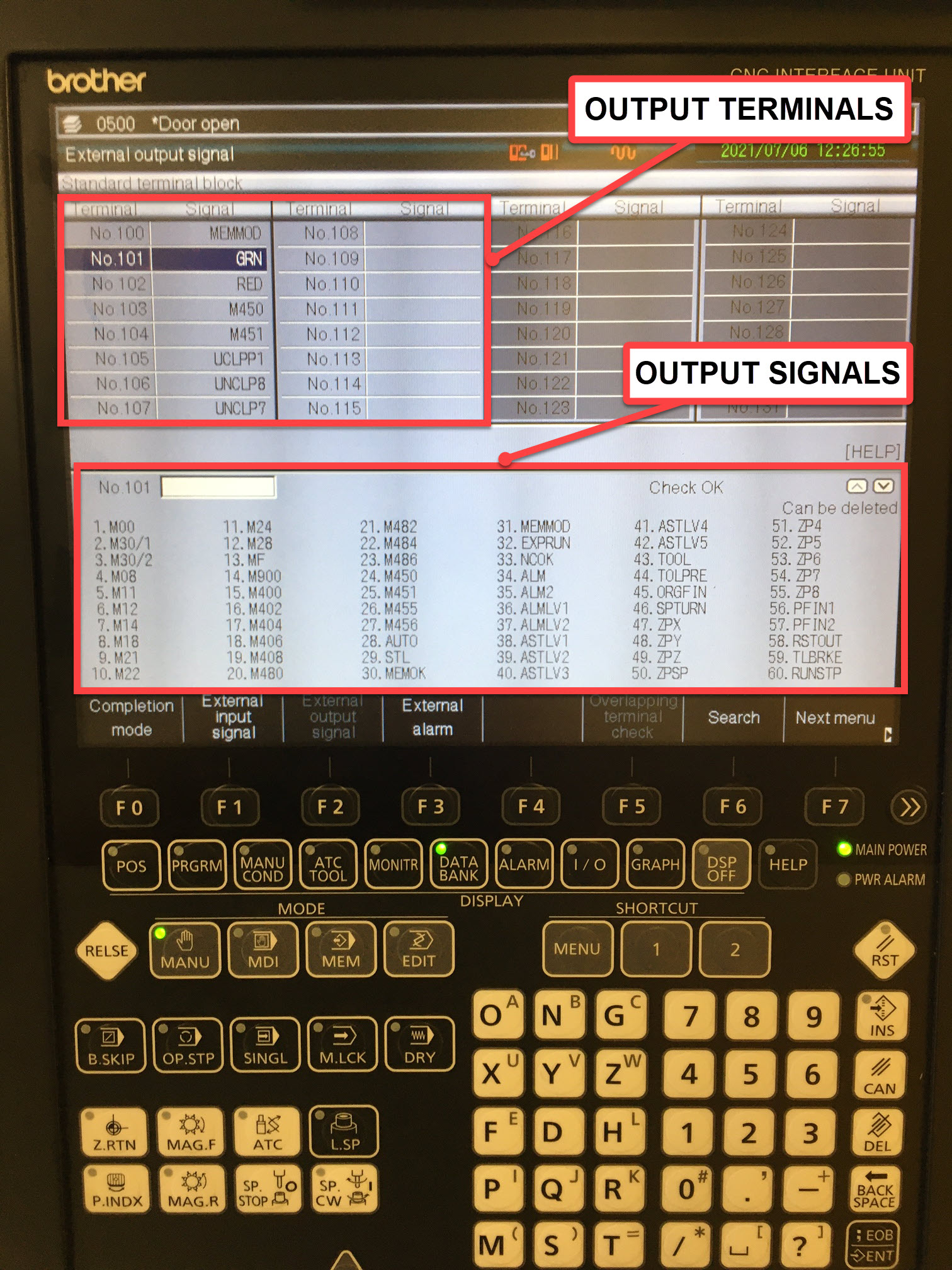
Pictured below is the External Output page. Each of the abbreviations in the lower list represents a specific machine function or state. Keep in mind there may be multiple pages of these abbreviations. The output terminals section represents the number labeled on the output terminal on the XTO terminal block.
Now that you have located the page from which external outputs are set, you can decide which signals you would like to set to the unused output terminals. In the example pictured below, the terminals 333, 334, & 335 were unoccupied in the machine's XTO terminal block:
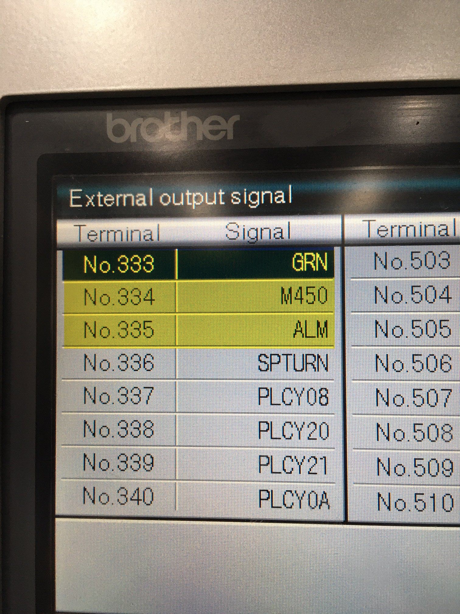
"GRN" is the signal for the green stack light, which is a good indication of machine activity. The output 333 is energized whenever the green light is on (regardless of whether there is a physical light on the machine or not). "M450" refers to the m code M450; which when seen in the parts program, send a momentary voltage pulse (24VDC) to the assigned terminal. This is an excellent way to get part count, as M450; has no other function for the machine. "ALM" stands for alarm, and is a good indication of alarm state, should you want to track that machine state.
Be sure to save any changes you've made to the XTO terminals!
Now that you have programmed the outputs on the XTO board, you can connect those signals to the analog inputs (AIN0-3) of your MachineMetrics I/O module. In general, we like to use certain inputs for certain states:
AIN0: UTILIZATION (GRN)
AIN2: PART COUNT (M450)
AIN3: ALARM (RED)
Adapter Script
Assuming you have connected the green light signal to AIN0, and the part count signal to AIN2, the adapter script below should work with your Brother IO Integration.
version: 2
variables:
  green-light-raw:
    - source: AIN0
    - resample: 0.1
    - min-delta: 1
  red-light-raw:
    - source: AIN1
    - resample: 0.1
    - min-delta: 1
  part-count-raw:
    - source: AIN2
    - resample: 0.1
    - min-delta: 1
  part-in:
    - source: AIN2
    - threshold: 3
    - rising-edge
    - count
  execution:
    - source: AIN0
    - threshold: 3
    - state:
      - ACTIVE: this
      - READY: true
conditions:
 system:
   message: Machine is in fault
   value:
     FAULT: alarm
data-items:
  - green-light-raw
  - red-light-raw
  - part-count-raw
  - execution
  - part-in
If you have any questions, please reach out to us at support@machinemetrics.com.
Comments
0 comments
Please sign in to leave a comment.